FOUR welding processes have been generally adopted for producing continuous welded rail in Japan: flash welding (FW), gas pressure welding (GPW), enclosed arc welding (EAW), and aluminothermic welding (TW). Gas pressure welds account for 35% of all welding processes, second behind alumino-thermic, which accounts for 44%.
GPW is a sort of solid phase welding. In this process, pressure is axially applied to rails and the butting section is heated by oxy-acetylene flame, to the specified temperature of 1200-1300°C. GPW does not use heavy equipment and produces highly reliable welds. However, it requires specialist skills, particularly for the rail heating process using a burner. As the number of well-trained welders is expected to decrease in the future, it is necessary to de-skill the rail heating process.
Various simplification and mechanisation methods have been examined, including the development of an automatic swing device for the heating burner, which was developed specifically to de-skill the heating process.
Intuitive skill
During GPW, the interface between butting sections must be heated intensively to obtain a good quality weld. However, this part of the process can sometimes lead to overheating of the rail surface. The heating burner therefore needs to be swung during the process to avoid overheating. There are no manuals on how to swing the burner, with the technique dependent on each welder’s intuitive skill.
This situation could lead to a fluctuation in the quality of the gas pressure weld. Two items were examined in order to de-skill the heating process:
- standardisation of the heating burner swing pattern, and
- development of an automatic heating burner swing device.
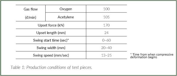
The gas pressure welds produced under the various welding conditions shown in Table 1 were evaluated to examine the influence of the swing pattern on the quality of the gas pressure weld. The start time of the burner swing means the time from when compressive deformation begins.
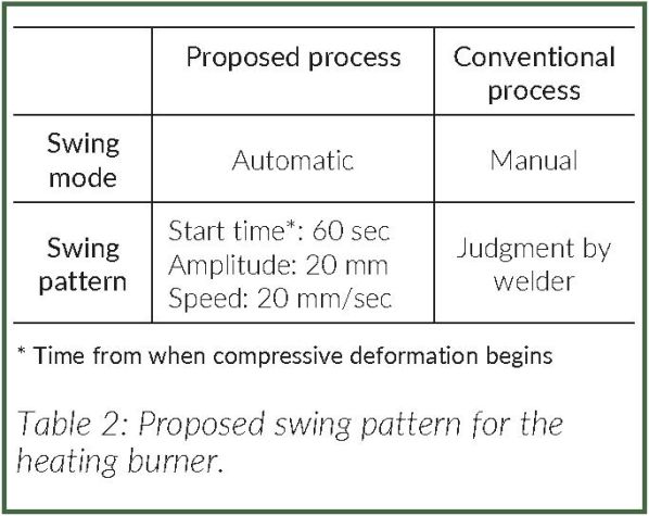
Standardisation of the burner swing pattern was examined based on these results and a suitable swing pattern for the burner was proposed. This both ensures sound welds, and avoids overheating of the rail surface during the heating process. Table 2 shows the proposed swing pattern for welding a JIS-60kg standard carbon rail.
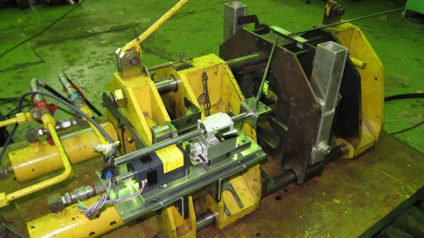
While standardising the joint welding process could reduce fluctuation in the quality of welds, the possibility for fluctuation would still exist while the operation was carried out manually. In view of de-skilling the process completely, an automatic swing device for a TGP-V type gas pressure welding machine was examined and developed to be capable of automatically reproducing the proposed swing pattern. Figure 1 shows the appearance and the structure of this device.
The heating burner is connected via a coupling rod to the swing block, which is reciprocated by means of a ball screw driving mechanism. This device also has the mechanism to allow the heating burner to follow the movement of the weld interface.
New processess
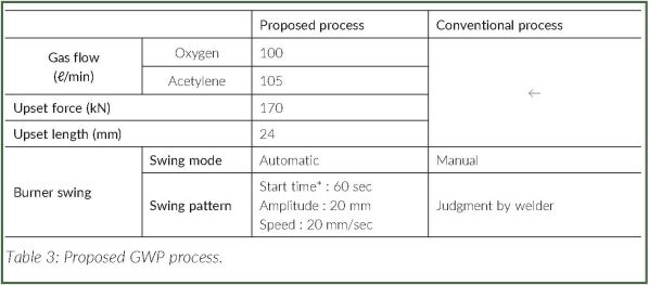
Based on these results, a new gas pressure welding process for rails was proposed. Table 3 compares the specifications of the proposed automated process with the conventional process.
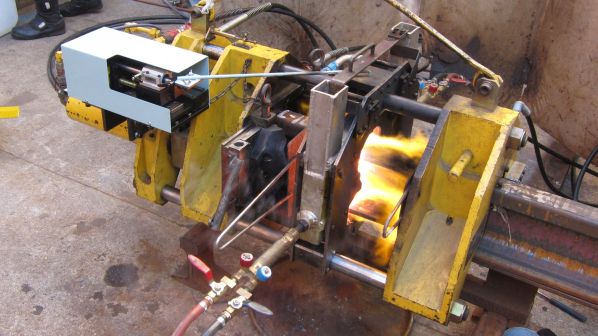
The specimens welded using the proposed process were evaluated to verify the applicability of the proposed process. In total, eight 1.5m long JIS 60kg standard carbon rails were prepared using the automatic heating burner swing device, according to the conditions shown in Table 3. Figure 2 shows the GPW being carried out with the automatic heating burner swing device and no problems were encountered in terms of workability of the GPW method.
In accordance with instructions on non-destructive inspection of welded rails, magnetic particle tests were performed on all the specimens. These were found to be sound and did not exhibit any linear indications.
Figure 3 shows the results of the static bending tests carried out on the specimens supported at two points located 1m apart with a load applied in the centre. In this figure, HU indicates the rail base tension condition and HD indicates the rail head tension condition.
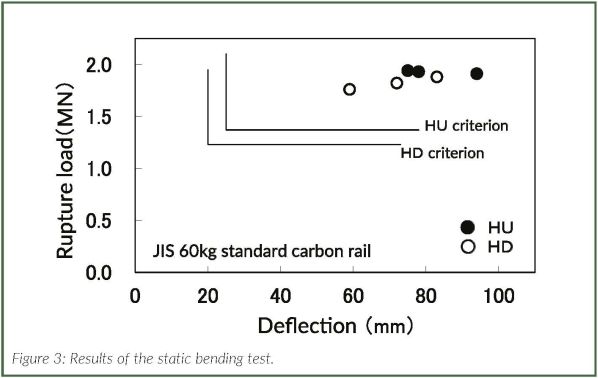
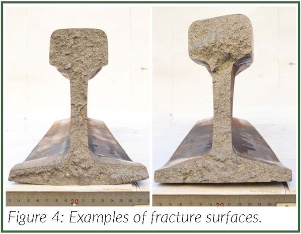
The rupture load and deflection were higher than those stipulated in JR specification for all the specimens. The condition of the surfaces of the fractures in the tested welds were good, as shown in Figure 4.
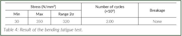
A four-point bending fatigue test was performed in the HU position to generate tensile stress in the rail base area of a specimen supported on a span of 1.3m (inner span: 0.15m), by applying a pulsating stress of a minimum of 30N/mm² up to two million times. The test results in Table 4 show that the specimen had the same fatigue strength of 320N/mm² stress range as the welded joint using the conventional process.
Hardness tests and micro-structure tests were carried out on the one remaining test weld. Neither test revealed any abnormal indications. According to the above results of respective evaluation tests therefore, it is considered that gas pressure welds produced with the proposed process could be introduced for practical use.