THE wheels of wagons and other railway vehicles are subject to the initiation and development of cracks below the tread surface due to cyclic mechanical loading. Manual non-destructive evaluation processes, such as handheld ultrasonic testing, are effective in finding internal cracks but are incredibly labour-intensive and require the vehicle to be taken out of service for inspection for a substantial period of time. Real-time automated detection of internal fatigue cracks could significantly improve efficiency, safety, and reliability by providing an effective way to monitor wheels in revenue service.
To date, research by MxV Rail, a subsidiary of the Association of American Railroads (AAR), has focused on automated cracked wheel detector systems evaluation under the Strategic Research Initiatives (SRI) programme. Previous systems have relied on piezoelectric-based ultrasonic transducers, which require a liquid-based couplant (water or gel) between the sensor and wheel to transmit the ultrasonic energy from the transducers into the wheel and receive any reflected signal. Without the couplant, the ultrasonic signal is weak, and defect detection is impossible.
While this piezoelectric-based ultrasonic technology is proven and performs well in detecting cracked wheels, the requirement for hundreds of ultrasonic sensors and liquid couplant complicates in-service deployment. Specifically, the couplant and glycol (to ensure the couplant does not freeze in winter) are consumables and require special handling both to deliver and recover them. These handling systems can be maintenance-intensive and limit the locations where cracked wheel detectors can be easily placed. In addition, installing such systems requires a stiff concrete track slab and special trackwork, which again limits the locations where cracked wheel detectors can be easily placed. Our current research therefore seeks to develop a contact-free alternative that is easy to implement and does not require couplant to detect cracked wheels in motion.
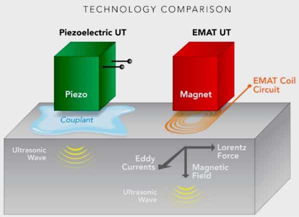
One method of ultrasonic testing that does not require couplant to inspect electrically conducting media is the use of electromagnetic acoustic transducers (EMATs). An electromagnetic field generated by a transducer, combined with an elastic field generated by material strains, creates ultrasound within the material adjacent to the transducer. Figure 1 compares the EMAT-based system with conventional piezoelectric-based ultrasonic inspection. EMAT uses a permanent magnet or an electro-magnet to introduce a static or biasing magnetic field, and a coil circuit to induce a dynamic electromagnetic field at the surface of conducting material. The electromagnetic and elastic fields in the surface of the material are then coupled to support the generation and reception of ultrasonic waves. Electromagnetic energy is converted to mechanical energy, and vice versa, across a small air gap of a few millimetres.
EMATs generate and detect ultrasonic waves using three transduction principles: Lorentz force, magnetisation force, and magnetostriction. The Lorentz force mechanism arises in all conducting materials, while the other two appear only in ferromagnetic materials. An optimal EMAT configuration depends on the desired elastic wave modes to be excited and detected. Energy transfer between electromagnetic and elastic fields requires a careful understanding of the coupling mechanism.
Many EMAT techniques that use bulk, surface and guided waves are commercially available for different applications. For wheel inspection, shear horizontal wave mode offered much greater potential than other guided wave modes. Shear horizontal ultrasound waves are polarised in plane to a sample surface and are a form of a guided wave, although they can be treated as bulk waves under certain conditions, such as over short propagation distances. With shear horizontal waves, particle motion is perpendicular to the entry plane and thus parallel to the wheel’s surface. The lack of a vertical force component makes the shear horizontal wave less sensitive to surface conditions, including material changes in the cold-worked surface area common in rail wheels.
EMAT method development
Initially, we explored the periodic permanent magnet (PPM) EMAT approach to generate shear horizontal wave modes in wheels. The wheelset was mounted on a structure that allowed the wheelset to rotate in position. The wheelset journals were partially supported on jack stands to reduce the weight and facilitate rotation.
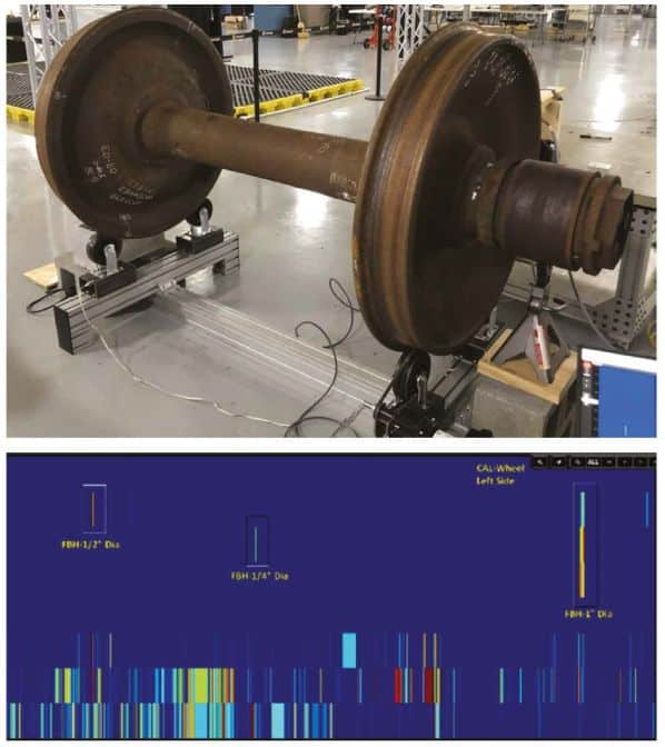
During the initial trials, it was determined that the PPM EMAT approach could not determine internal wheel defects and exhibited poor detection capabilities with extensive noise. In addition, the wheel flange limited the dimensions of the sensor, reducing the scope for practical application. Figure 2 shows the laboratory setup for in-motion PPM EMAT testing and the C-scan result for a calibration wheel with reflectors of a defined size. While the test could detect different-sized reflectors drilled into the wheel tread, the most significant challenges included inserting shear horizontal energy directly into the wheel material, low signal-to-noise ratio, and sensor construction cost.
The inability to penetrate the wheel material and obtain reasonable detection resulted in exploring a magnetostrictive EMAT approach with a magnetostrictive patch applied at the wheel/rail contact. A magnetostrictive EMAT sensor with a meander coil driven at a wavelength of 625kHz could penetrate the wheel rim to a depth of 6.25mm. A thin (0.25mm) highly magnetostrictive strip made of iron-cobalt (FeCo), measuring 50.8mm by 50.8mm, was placed on top of the coil and was pressure coupled to the passing wheel. The FeCo strip also protected the EMAT coil underneath, which generates ultrasound on the strip that is subsequently transferred into the wheel tread.
Although the magnetostrictive EMAT approach improved the signal-to-noise ratio by a factor of 10, it was obtained at the cost of losing its non-contact nature. To evaluate the magnetostrictive EMAT approach, several in-motion tests were performed using a 3.65m section of panel track and five wheelsets obtained from the Facility for Accelerated Service Testing (Fast) in Pueblo, Colorado. These wheelsets had varied size reflectors (notches and flat bottom holes) machined into the wheel tread and wheel defects such as sub-surface fatigue cracks and broken rims previously characterised by conventional ultrasonic measurements.
The EMAT system demonstrated that the magnetostrictive shear horizontal wave technique could detect internal wheel defects. A previously undetected flaw was also found during testing. The system found horizontal defects (parallel to the tread surface), which is essential because most cracks, including vertical split rims, initiate horizontally.

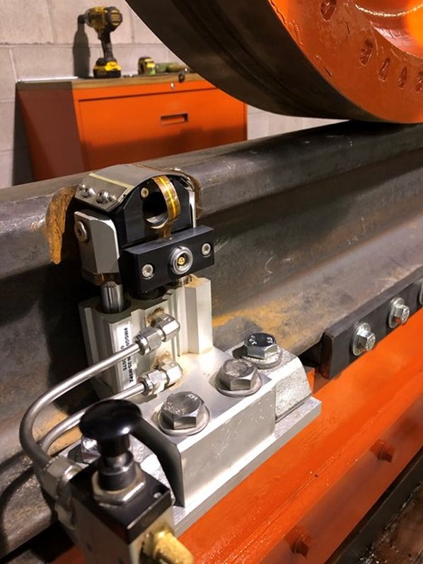
Figure 3 shows the magnetostrictive EMAT sensor mounted on a notched rail installed on a yard track. Mounting the sensor on the base of the rail avoids the need for extensive foundation work in the revenue service environment. The lack of foundations would also allow the sensor assembly to be removed when track maintenance work is required at the installation site. To cover the circumference of a wheel up to 965.2mm in diameter, the system would require four to five notches milled 28.75mm into the field side of the rail. Each notch would be about 127mm long, and the centre-to-centre spacing would be around 508mm. The rail field side positioning allows the sensor to inspect a 50.8mm band inward from the rim face. It also means that coverage will depend on track gauge variation, wheelset flange back clearance, and wheelset lateral position. Maintaining standard track gauge is critical because a wider gauge could limit exposure of the wheel tread to the sensor head.
As developed, the EMAT technique has the advantage of using a limited number of stationary rail-mounted probes to inspect a 50.8mm-wide band of wheel tread. It also avoids the need for extensive foundation work when installing the system on the operating railway, and eliminates the need for liquid couplant.
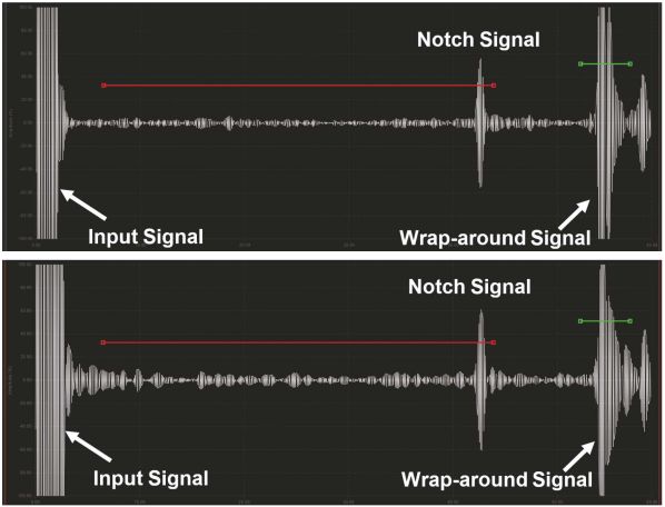
Continuing research will address the system’s performance for varied wheel surface and wear conditions, gauge clearance, and lateral wheelset position. Understanding the survivability of the sensors, the EMAT sensor assembly and notched track in a typical railway environment is also crucial. Currently, MxV Rail is using the rolling load fixture for accelerated testing of the EMAT sensor assembly, and notched rail as shown in Figure 4. The notched rail has sustained over 30 million gross tonnes, and no issues have been identified. Different versions of the EMAT sensor are also being developed and tested, and one of the sensors has sustained 20 million gross tonnes without any damage or compromise in the ultrasonic signal quality. Figure 5 shows the comparisons of EMAT signals before and after cyclic testing, inspecting a wheel with a notch in the tread. The EMAT signal results were almost identical, indicating no deterioration in signal after the cyclical tests.
Several tests are being designed at MxV Rail’s Pueblo facility to understand the effects of heavy axleload traffic with the sensor exposed to various wheel profiles and surface conditions. This applied research will be combined with the manufacturer’s enhancement of the performance, durability and manufacturability of the hardware before the deployment of a prototype system.