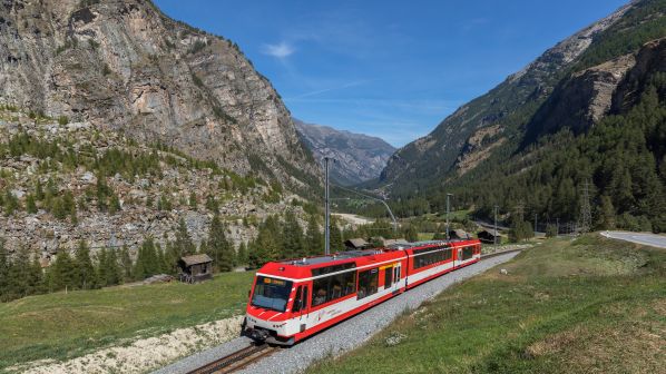
WITH more than eight million passengers per year, Matterhorn Gotthard Railway (MGB) is one of the largest operators in Switzerland and one of the country’s most spectacular railways.
The 144km network passes through the fascinating countryside of Disentis over the Oberalp Pass at more than 2000m above sea level to Andermatt. From there, the line continues via Realp through the Furka Base Tunnel to Oberwald, and via Brig and Visp to Zermatt below the Matterhorn.
In Disentis, MGB connects with the Rhaetian Railway (RhB), where together the two companies run the Glacier-Express between Zermatt, Chur, Davos, and St Moritz.
The line supports tourism in the region. And with the expansion of the partially single-track lines to double track, rail transport has become even more appealing to visitors.
“Efficient management of the rail network requires know-how and the right solutions,” says project manager, Mr Jean-Pierre Waldmann
MGB’s engineering section asked Siemens to plan and implement an upgrade of the existing control system for the traction power supply, including the network infrastructure.
“Efficient management of the rail network requires know-how and the right solutions,” says project manager, Mr Jean-Pierre Waldmann, who is responsible for technical infrastructure at MGB. “We want to know what is happening on the line at all times.
That applies equally to tracking trains on their routes, to fast location and elimination of faults along the line and in the requirement-based traction power supply.”
Highly complex
The work involved replacing older devices used on the network infrastructure with components that are not only modern, but also easier to manage and maintain. The previous structure was highly complex with a duplicate network consisting of separate switches and routers. However, the entire system was susceptible to failure if malfunctions occurred.
As a result, Mr Raymond Püntener, the Siemens project manager responsible for the MGB project, planned a solution based on two Layer 3 switches - for faster and more flexible modification of the network. “The redundant design makes one virtual switch out of two devices,” he says. “If one device fails, the other device automatically takes over its function.”
Siemens decided to use the Ruggedcom RX1500 for this solution. The RX1500 is a multi-service network component that combines the ethernet functions of a switch, router and firewall with WAN connectivity. The robust ethernet switch and TCP/IP router is designed for use in high-performance automation networks. The combined device ensures high reliability with hot-swappable media modules and power supplies. The primary additional benefit for the user is flexible expansion with the media modules. Also critical in the decision to select the RX1500 was the product’s robust design, capable of withstanding high levels of electromagnetic interference, shock and vibration, along with flexibility in the input voltage range and the extended temperature range without cooling fans.
The control system network was divided into several virtual LANs (VLANs), which act as the process LAN for checking the booking or customer information systems. A Layer 3 switch, like the Ruggedcom RX1500, is ideal for this task. In addition, the Virtual Router Redundancy Protocol (VRRP) feature incorporated into the RX1500 ensures network availability.
If a malfunction occurs on a line section, the affected section is disconnected without disturbing the remaining power system operation.
At MGB, the two RX1500 switches at separate locations became one logical unit, a virtual router. The existing structure was initially broken down and the process LAN was subdivided into 10 VLANs. The traction power supply is controlled at Brig and Glisergrund stations, which are around 4km apart and redundantly connected via fiber-optic cable. If one of the RX1500 switches fails, the other takes over the gateway function immediately ensuring continued network operation.
Employees at the Brig power system control center constantly monitor the quality of the electricity supply. Individual switching of the overhead lines is carried out by the control system while instructions are routed through the control system network to the relevant substations. Along the line, the control centre monitors and controls the 44 stations, with seven stations connected together to form a single VLAN. If a malfunction occurs on a line section, the affected section is disconnected without disturbing the remaining power system operation. And with messages sent directly to the control system, an employee can send the service team straight to the affected line section.
Commissioning
With upgrades to the existing equipment infeasible both technically and economically, the approximately 10-year-old hardware was replaced with new systems at both Brig and Glisergrund. Siemens first set up the hardware and software in a testing environment with the simulation demonstrating perfect interaction of all components and the arrival of the switching commands at the destination as planned.
The project started by replacing the installed systems with a leaner hardware infrastructure. “Because we had built a redundant system (A+B), we were able to convert system A of the power system control center to the new IP structure first and test it,” Püntener says. “Once we had a successful result, system B was also converted.”
Another advantage of the system’s simplified routing is the reduction in maintenance. A service technician can diagnose the control system at any time through secured remote maintenance via the internet. Personnel can remotely set values and transfer program updates. This results in shorter response times and in some cases, avoids service call-outs altogether. According to Waldmann, having one point of contact for any service-related inquiry is also a big advantage.
He adds that the new intelligent power supply network supports the stringent requirements of a future automated railway network.
The network integrates existing infrastructure with the new hardware and software components at Brig and Glisergrund stations. At the core of the new infrastructure are two Layer 3 switches the routing functions of which enable communication between the various IP subnetworks and the high-performance automation network. The result is improved fault detection, accelerated power system recovery, and increases in the reliability of power supply throughout the entire MGB network.