LATERAL stability and durability of continuously welded rails on ballasted track are crucial for high speeds and loads. Maintaining track stability is therefore becoming increasingly important as global warming intensifies and the potential for track buckling during prolonged high temperatures increases.
Track buckling is caused by the superposition of three adverse factors: high compressive forces in the rail, weak points in the ballasted track, and the dynamic effects of the train traffic, which reduces the resistance of the superstructure due to the forces and vibrations introduced.
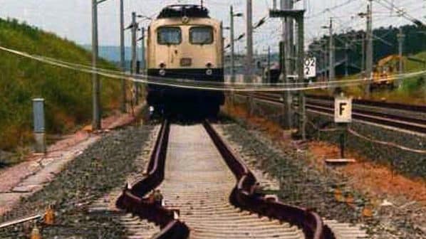
Buckled track typically has large short-wave lateral misalignments that lead to derailments when a train passes over them. For example, an average of 38 train derailments per year were recorded in the United States between 1998 and 2002 because of track buckles. The costs incurred during this period amounted to $US 55m. In June 2016, a freight train derailment also occurred in Germany between Gaildorf West and Schwäbisch Hall-Hessental due to track buckling, causing total damage of €1.74m.
This is why it is even more necessary to develop and use innovative technical solutions that can guarantee the safety of the track even at high rail temperatures.
Lateral track stability during rail heating is treated with the energy method in the calculation procedure developed by H Meier. The basic parameters of lateral track stability are defined as lateral sleeper resistance (LSR), rail profile, curve radius, lateral track misalignments resulting from the operational load, and frame stiffness. The theoretical moment of inertia ITH of the track grid represents the frame stiffness, which can be determined experimentally in the laboratory and is used as a discrete value in Meier’s formulae.
However, the theoretical moment of inertia alone cannot precisely reproduce actual track force deformation relationships since the theoretical moment of inertia is not constant in reality but depends on the lateral displacement (corresponding to the lateral track misalignment or deflection in the test) of the track grid as well as on defect length. The theoretical inertia moment is mainly influenced by the rail profile, sleeper design, and sleeper type as well as the torsional resistance of the rail fastening system.
There are various ways to prevent track buckling. However, the question is which solutions are technically effective, economical, and as simple as possible to apply. The quickest measure is to implement a temporary train speed restriction to minimise the dynamic effects. However, this leads to delays, operational disruption, high costs, and ultimately to a loss of image for the railway and is therefore not expedient.
The second possibility is to increase lateral sleeper resistance by using heavier concrete sleepers with profiled sides such as scallops and sleeper pads or by using sleeper anchors. Other possible measures include reducing sleeper spacing, using high-quality ballast, ballast bonding, or widening the ballast shoulder. Such solutions are fine on new lines or during track upgrading but are costly and take time to implement on existing lines.
A third possibility is to increase track stiffness by using fastenings with a high torsional resistance (HTR) or by laying a particular design of sleeper such as Y-shaped steel sleepers or ZSX-sleepers. However, the installation of special, stiffer sleepers is expensive and cannot be implemented quickly.
Using heavier rail profiles increases track stiffness due to the higher moment of inertia, but higher compressive forces are generated due to the increased cross-sectional area of the rails. Thus, heavier rails per se do not exert a positive effect on lateral track stability.
Stiffness
Based on this understanding, Vossloh set about developing rail fastening components that help to increase torsional resistance, thereby improving the stiffness of concrete sleeper track. After several years of intensive research and development, Vossloh’s M7 novel tension clamp and HTR angled guide plate have been undergoing field testing since 2022 and are now ready for series production.
The innovative design of the new components optimises several technical properties, including greater torsional resistance and lateral stiffness. The simultaneous effect of these two main parameters exerts a decisive, positive influence on the theoretical moment of inertia of the track, as shown in the following investigations.
In the event of track buckling, there is a sudden lateral movement of the two rails. As a result, the sleepers in the ballast are displaced laterally and the rails rotate in relation to the rail supports of the sleepers. The higher the torsional resistance of a rail fastener, the lower the risk of track buckling. The torsional resistance of the fastening system can be determined under laboratory conditions according to EN 13146-2. The sleeper is fixed immovably during the test, and the fastening system is mounted on a short rail section. A transverse force is applied to the rail foot and rotated by a certain amount in both directions. The resulting torsional resistance is evaluated in kNm for a rail rotation of ±1°. However, neither the EN 13146-2 test standard nor the EN 13481-2 requirement standard define values regarding the magnitude of the torsional resistance.
The torsional resistance of the W14 rail fastener was determined by comparing eight different superstructure types in Vossloh’s test laboratory in Werdohl, Germany. To ensure comparability of the test results, during rail fastening tensioning a uniform torque of 250Nm was applied to the sleeper screws.
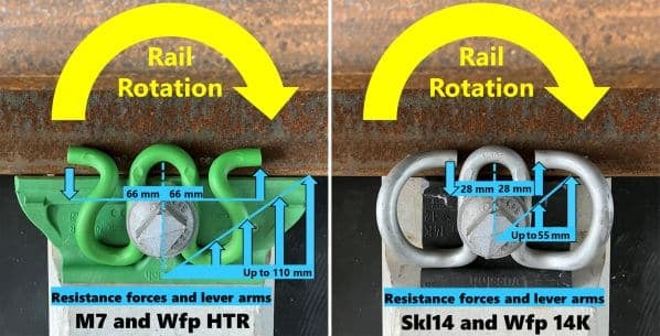
The significant improvement in rail fastening torsional resistance is due mainly to the innovative design of the new components. The exact improvements in torsional resistance are depicted in tables 1 and 2. Compared with a conventional tension clamp and angle guide plate, the novel M7 and HTR show a longer lateral resistance force lever arm of 2.4 and 2, respectively (Figure 1). The extended lever arm combined with increased lateral stiffness due either to the M7’s S-shaped tension clamp arms or the specially designed edge area of the HTR results in a significant increase in torsional resistance.
Torsional resistance is not sufficient as the sole comparison criterion in an evaluation of lateral track stability. Track lateral deformation is influenced by the interaction of the rails, rail fastening components, and sleepers. This makes it necessary to analyse this combined behaviour in large-scale tests.
The relationship between track bending under defined boundary conditions and the associated force leads to the track’s so-called theoretical moment of inertia. This is a specific value, with which the lateral stiffness of the track itself is described, without consideration of the LSR.
Experiments to determine the track’s theoretical moment of inertia ITH for the different types of superstructures with B70 sleepers and rails type 60E2 have been conducted under dry conditions at the Technical University of Munich’s Institute of Road, Railway and Airfield Construction laboratory where different bearing distances and their influence is investigated. Fastening systems for B07 sleepers have also been studied.
The following types of superstructure with the W14 fastening system were analysed, whereby every version was examined with two distinct types of rail clamps: common Skl 14 and innovative M7:
- Wfp 14 K with Zw 687a
- Wfp 700 HTR with Zw 687a
- Wfp 14 K 900 with Zw 900, and
- Wfp 900 HTR with Zw 900.
The determination of these characteristic values was obtained by using a section of track with nine sleepers. The track’s vertical bearing is as frictionless as possible through a track ball bearing on top of steel plates. With a sleeper spacing of 60cm, the spacing between the lateral bearing results in 4.8m (see Figure 2). For a lateral bearing, the end faces of the sleepers at the end of the track section were used. The rail fastening was uniformly tensioned to 250Nm.
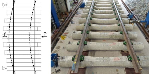
A centrally arranged force application was applied to the end face of the centre sleeper on the support-free side of the track. During the tests, the track deflection was continuously increased in steps up to 25mm. In each case, increments of 5mm were generated three times before continuing with the subsequent larger deflection. The tests were evaluated using an average of three loads with the same deflection.
In both cases (with hard rail pad Zw 687a and elastic rail pad Zw 900) the rail fastening with a W14 angled guide plate and a Skl 14 tension clamp was chosen as the reference system.
In general, higher values of the theoretical moment of track inertia occurred with the HTR angled guide plate and the combination of HTR and M7 tension clamp compared with the standard angled guide plate and tension clamp. This applies to the test results with hard pad Zw 687a and the test results with elastic pad Zw 900.
Variations will be compared using measured values at a 10mm deflection, because this deflection was measured for every system and resembles a value approximately in the middle of ITH.
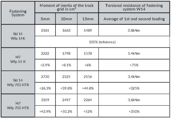
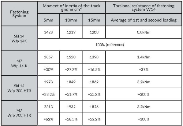
In the case of the systems with hard rail pad Zw 687a, the use of the M7 and conventional guide plate shows an ITH increase of 8.1%. Using the HTR with conventional tension clamp leads to an ITH increase of 39.8%. Combining the novel HTR with M7 results in a 50.2% increase in ITH (Table 1).
Similar behaviour appears for systems with the Zw 900 elastic rail pad. The use of M7 with conventional angled guide plates results in a 27.2% increase in ITH. The use of the Skl 14 tension clamp together with the HTR results in a 51.7% increase in ITH. The combination of M7 with HTR shows a 58.5% increase (Table 2). With these values, the critical temperature increase of the rails until track buckling could be determined with Meier’s Theory.
In summary, the rail fastening system with higher torsional resistance (M7/HTR) leads to an increase in the theoretical moment of inertia ITH of a track section compared with a conventional fastening system (Skl 14/Wfp 14). This results in higher resistance against track buckling. With the installation of the novel components M7/HTR, it also could be possible to dispense with widening the ballast shoulder in certain cases and the necessity to impose temporary speed restrictions.
Advantage
The M7 and HTR have a clear economic advantage compared with other measures for improving lateral track stability, such as sleeper or ballast replacement. The cost of replacing tension clamps and angled guide plates is many times lower and the remaining, existing rail fastening components such as rail pads and screws can continue to be used. Even under the imminent danger of track buckling, when quick action is required, the newly developed rail fastening components can be installed in the track with relatively little effort during night-time possessions when the rails are cooling down. And finally, compared with other temporary measures to prevent track buckling such as speed restrictions, line closures, and “white” rails, the M7 and HTR can provide a permanent and sustainable solution.
*This article was written by Timo Wastlhuber and Prof Dr-Ing Stephan Freudenstein with the Institute of Road, Railway and Airfield Construction at the Technical University of Munich, and Dr-Ing Dimitre Iliev and Winfried Bösterling with Vossloh Fastening Systems.