RAIL maintenance to prevent rail breakages is critical for railway safety. Squat and gauge corner cracks due to rolling contact fatigue (RCF) are railhead failures caused by repeated train passage. Transverse cracks propagating in the rail dimensional direction originating from squat and gauge corner cracks at railheads (head transverse cracks) account for approximately 40% of Japan’s rail breakage between 2014 and 2018.
Corrosion accounted for 25% of this total while weld defects were responsible for 16%, joint hole split 11%, and others 5%.
There has been increased research into crack propagation to maintain rails appropriately and several sophisticated crack propagation models have been proposed. However, few studies have examined the propagation characteristics of transverse cracks by evaluating full-scale rails.
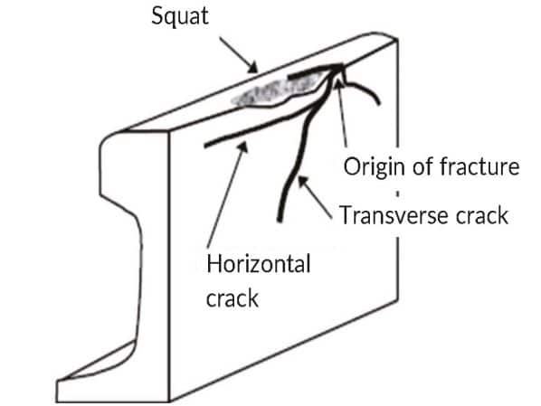
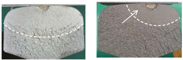
Figure 1 shows the outline of a squat on a railhead. During squat development, because of the RCF damage on the railhead, horizontal crack propagation occurs and branches towards the bottom of the rail as head transverse cracks. In principle, head transverse crack propagation is strongly affected by the tensile stress condition in the railhead by the train load, the residual stress which occurred when the rail was produced, and the axial rail load. A hardened heat-treated rail is used in curves to prevent the railhead from wearing through wheel contact.
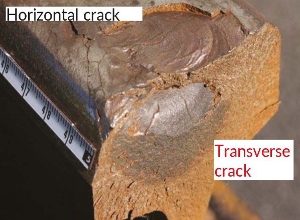
However, transverse cracks originating from a gauge corner crack on these rails have often occurred because of insufficient wear (Figure 2). To manage these problems, railways conduct periodic visual and non-destructive ultrasonic inspections or rail replacement. For timely inspections and replacement of rails, there is a need for research into crack propagation.
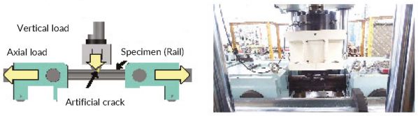
For this research, rail fatigue bending (transverse crack propagation) tests were conducted on various rails with an artificially created crack in the railhead to investigate the transverse crack propagation rates and tendencies. The railhead residual stress inside the rail was then measured to examine the influence of residual stress on the transverse crack propagation rate. Finally, a method was developed to estimate transverse crack propagation under various railway conditions using the finite element method (FEM).
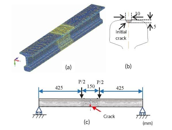
Several parameters affect the propagation rate of head transverse cracks, such as heat treatment, residual stress, and crack position. To ascertain the propagation rate of the head transverse cracks of various rails, transverse crack propagation tests were conducted on actual rails with artificially created cracks in the rail surface (Figure 3a), with the railhead facing downwards.
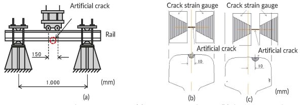
The stress amplitude was 100N/mm² to accelerate crack propagation. Transverse crack propagation tests were performed on various actual rails, such as heat-treated rails, annealed rails (where the heating process reduces residual stress), or rails with artificial off-centre crack positions. Artificial cracks - semi-circular slits with a radius of 5mm - were created on the rail surface in the centre or off-centre in the rail dimensional direction of each specimen (Figures 3b and c). Transverse crack depth was investigated by attaching a crack strain gauge to both sides of the artificial crack. As the crack propagates, the electron beam breaks off, generating a signal each time. The crack length obtained by the strain gauge was multiplied by the elliptical flattening ratio by reading the elliptical shape of fatigue cracks after each test to obtain the transverse crack depth.
Figure 4 shows the results of the transverse crack propagation tests. The horizontal axis shows the number of loading cycles, and the vertical axis shows the transverse crack depth from the rail surface. Two examples of the fractured surface after the test are shown in Figure 5. The test results are as follows:
First, all specimens were broken. The propagation rate of the transverse crack increased as the transverse depth increased in all results.
Secondly, Figure 4a shows the results for standard and heat-treated rails. The effect of heat treatment (rail grade) on the propagation rate of the transverse cracks was small compared with that of other factors described later.
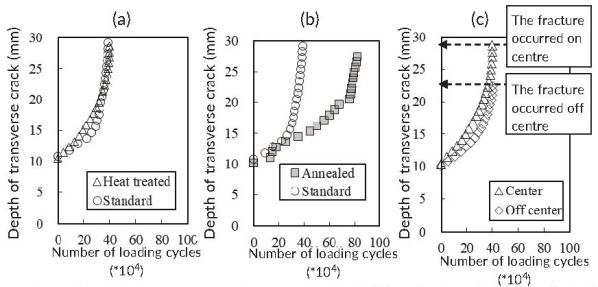
Thirdly, Figure 4b shows the result for standard and annealed rails. The propagation rate of transverse cracks in rails that had been annealed to reduce the residual stress was less than half that of the standard untreated rails and significantly differed.
Finally, Figure 4c shows the result when the artificial crack was at the centre and off-centre of the railhead. There was no apparent difference in the propagation rates of the transverse crack tendency between both rails. However, the fracture occurred in a shallower position off-centre than in the centre.
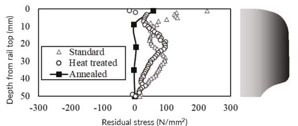
The railhead residual stress inside the rail was measured using the Modified Internal Residual Stress (Mirs) method to investigate the influence of residual stress on the transverse crack propagation rate. A vertical hole was made downwards from the centre of the rail surface, and the diameter of the hole was measured precisely using a micro-air probe. Next, the periphery of the hole was cut off in a cylindrical shape to release the residual stress. Finally, the diameter of the hole was measured again to determine the residual stress from the difference in the diameter of the hole before and after cutting.
Figure 6 shows examples of the measurement results. Overall, tensile residual stress was observed at a depth of 0–50mm, and the average values in that range were 66, 72, and 11N/mm² for a standard rail, a heat-treated rail, and an annealed rail (roughly measured by the cutting method), respectively. The residual stress measurement and the transverse crack propagation test results were considered. The residual stress of the non-annealed rail is considerably higher than that of the annealed rail at the same depth, indicating an increase in the crack propagation rate due to the larger residual stress.
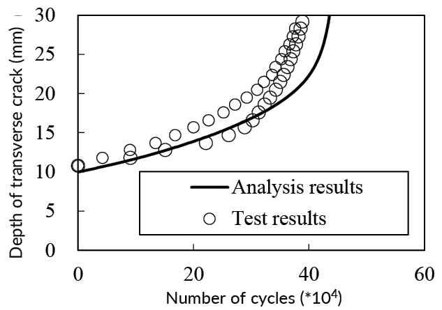
FEM analysis was conducted to understand the propagation rate of a transverse crack of the railhead using the virtual crack propagation method and analysis system Finas/Crack with automatic meshing and the large-scale nonlinear structural analysis system Finas/Star. Analysis simulating the transverse crack propagation test was performed to verify the validity of the analysis method.
The initial crack formed a 5mm-deep semicircle in the longitudinal centre of the rail (Figure 7). Figure 8 shows the relationship between the number of loadings and the transverse crack depth. Because the analysis results correlated well with the test results, this method effectively predicted the transverse crack of the railhead.
This examination suggested that the proposed analysis method could be used to predict the propagation of a transverse crack in a rail. In reality, various stresses in the railhead occur on the railway, such as the train load bending stress, residual stress, and axial rail stress due to temperature fluctuations. Verification by tests on actual rails by considering complex stress conditions, such as train loads and axial rail stresses, has been performed (Figure 9).
The process is as follows. First, input the track (track alignment and track structure conditions) and vehicle conditions into the Simpack vehicle motion analysis software to calculate the wheel load lateral pressure, the wheel position, and the contact area between the wheel and the rail of a passing vehicle wheelset.
Secondly, input shape, angle, and position of the crack, axial force and residual stresses, crack propagation characteristics, and the results obtained in the first step into the Finas/Crack transverse crack propagation analysis system to determine the relationships between crack propagation, stress intensity factor range, and stress ratio.
Finally, set the annual passing tonnage (number of trains per year × train weight) and temperature fluctuations to calculate transverse crack propagation using the results obtained in the second step.