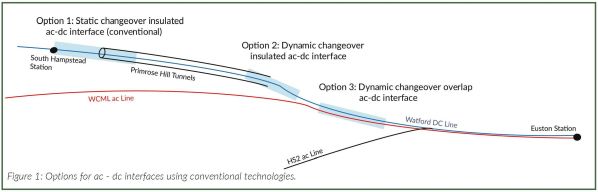
THE approach to London Euston station at the southern end of Britain’s West Coast Main Line (WCML) (Figure 1) has a mixture of 25kV ac overhead and 750V dc third rail electrification using the same tracks, so there is a need to isolate the dc from ac to minimise dc stray currents. Significant changes are required to the electrification network associated with the redevelopment of Euston station for the HS2 project which has a direct impact on the London Overground dc line from Watford to Euston.
In assessing options to maintain operation of the Watford line, several solutions were proposed to upgrade the infrastructure (Figure 1) comprising:
- the use of conventional static changeover at South Hampstead which requires modifications to Primrose Hill tunnels
- dynamic changeovers at the verge of Primrose Hill tunnels, and
- dynamic changeover on the WCML main line.
In the second and third options, dynamic changeover is required to minimise disruptions on the WCML. However, all these options involve costly infrastructure changes, with significant disruption during construction as well as train operation reliability issues.
Arcadis has proposed a fourth option (Figure 2) based on powering the Watford trains by onboard battery between Primrose Hill tunnels and Euston. The battery will be charged from the third rail during normal operation north of Primrose Hill tunnels.
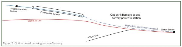
This solution not only avoids expensive infrastructure changes but will also simplify the track layout around Euston and provide greater flexibility and reliability during the remodelling of Euston station. The proposed battery train solution has been assessed using Arcadis’ in-house design simulator to demonstrate its feasibility and to optimise the battery size required.
The battery option obviates changes to the overhead electrification, signalling or track layout, and the third rail can be removed. No ac-dc interface or additional lineside equipment, such as balises, will be needed, although insulated rail joints must be installed to isolate the ac from dc tracks on the Watford line. No changes are required to the current accessibility and maintainability rules and practices.
However, battery train operation has two risks: running out of charge and battery failure. To mitigate the first risk, a battery charging facility could be installed at Euston or between Euston and Primrose Hill tunnels. To avoid battery failure, multiple battery packs could be added to each traction package, with the battery pack integrated with the traction package to feed two motors only.
Additional mitigation could involve adding a smaller emergency battery to the vehicle which can be used to power the train for short distances at low speeds in case the main battery fails or has discharged. Generally, a malfunction of the battery can be mitigated by the deployment of dual supply trains and manual changeover.
The energy consumption of the class 378 EMUs operating between Euston and Watford has been simulated over 5.14km with one stop at Euston. The trains have three motored cars, each equipped with three 200kW traction motors. The dwell time at Euston was assumed to be 20 minutes and the train auxiliary load was estimated at 100kW. Simulations have been performed to optimise the battery size and traction performance.
Battery train operation has two risks: running out of charge and battery failure.
A 3-tonne energy storage battery system would be sufficient to power the train throughout the round trip. As the battery is discharged at a maximum power of 1600kW, the train drive cycle includes phases with limited acceleration, possibly leading to a longer travel time. A 4-tonne battery is required to match the performance of normal overhead supply. However, a 3-tonne battery would be optimum to achieving the desired performance while minimising the size and cost of the battery.
Another option considered is the use of an onboard supercapacitor working in conjunction with options 2 or 3. In this option gaps longer than a train length can be introduced between the ac and dc tracks and the train is powered by the onboard supercapacitor whilst operating within the gap. A 2-tonne supercapacitor energy storage system would be adequate to power the train through short gaps and the supercapacitor has been specified to cover a 224m gap, which will enable the dual operation train to switch from dc to ac when leaving Primrose Hill tunnels.
Supercapacitors would be ideal for this because, unlike batteries, they have low energy density but are capable of delivering very high power for short durations. However, the additional infrastructure changes for options 2 or 3 are still required if either of these options is chosen. Furthermore, in employing this option, the train must have triple supplies: ac, dc and energy storage. All lineside detection kits will need to perform the dynamic changeover. The trains must be equipped with shoe-gear, pantograph and transformer, and energy storage, in addition to an antenna or reader to communicate with lineside equipment in addition to a beacon or balises on the ground. Given these requirements, this option is unattractive.
Option 1
A static changeover overlap ac/dc interface requires a long dual-fed ac-dc overlap section between the ac and dc electrification areas, over which the changeover takes place. The overlap interface can be created using a static changeover incorporating two isolation transformers and double insulated rail joints per track.
A static changeover at South Hampstead station can be achieved if overhead catenary is installed through Primrose Hill tunnels with the ac/dc changeover located at the station. Catenary would also need to be installed inside the tunnels leading to the North London Line with the overlap interface located at South Hampstead station.
Option 2
A dynamic changeover with an isolated interface would require an unpowered isolation gap between the ac and dc electrified areas through which the trains must coast. To provide a smooth transition on the move, a short section of earthed contact wire must be installed in the dc area beyond the isolation point to provide the necessary kinematic support to the pantograph while the train is moving and when the pantograph is being lowered during the transition from ac to dc or raised in transition from dc to ac (Figure 3).
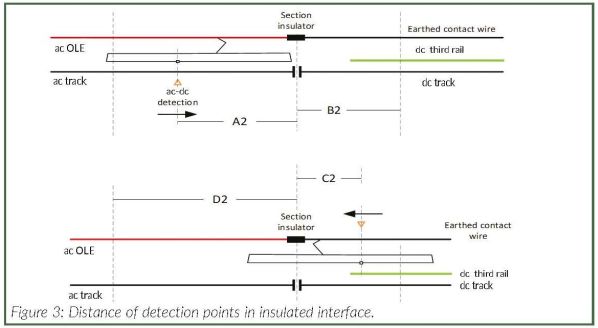
For trains with more than one pantograph, only a single pantograph would remain in contact with the exposed live part of the contact wire. Isolation is achieved by installing one or more insulated track joints per track to isolate the ac rails from dc rails. An overhead section insulator must be installed at or before the neutral zone, to mark the end of ac electrification. The third rail starts at the end of the neutral zone. The length of the neutral zone is chosen to optimise the minimum speed required, the level of permissible dc stray currents, and the infrastructure restrictions of the site.
The neutral zone can be shorter than a train length, in which case a train passing through the section will temporarily bridge the ac and dc tracks, allowing dc stray currents to flow for a short period. The maximum time can be determined by considering the minimum train speed and the length of the neutral zone.
To avoid a train becoming stranded in the neutral zone, the detection point in both directions must be as close as possible to the isolation interface (Figure 3). Furthermore, the distance between the stop signal and the isolation interface must allow a minimum speed at the entry to the interface.
To minimise arcing, the design should consider the pantograph transition time in conjunction with the catenary distances and whether the transition takes place with full load train current.
During a transition from ac to dc, the vacuum circuit breaker (VCB) must be opened before lowering the pantograph, and during a dc to ac transition the VCB should be closed after the pantograph has been raised. Furthermore, only the VCB or high-speed circuit breaker (HSCB) should operate at any particular moment, provided the supply is available. It is also recommended that during a transition from dc to ac the HSCB must remain closed until the supply is lost. A safety distance must be added in both directions, and the overhead electrification distance on the dc side must be as long as possible. This minimises the risk of raising the pantograph too early during a transition from dc to ac, or lowering it too late on a transition from ac to dc. This would allow adequate time for manual intervention should a problem occur. The safety distances on the dc side must ensure that the pantograph does not infringe the loading gauge when the train is transitioning from ac to dc. The detection distance A2 in ac to dc transition is more critical than the distance C2 in dc to ac transition. This is because in ac to dc transition, the pantograph must be disengaged from the live wire before reaching the section insulator and entering the neutral zone to minimise arcing. During dc to ac transition, ac current is not drawn until the pantograph is raised and the VCB has closed which reduces the risk of arcing. Beacons or balises are used for train detection for both the overlap and insulated interfaces (options 2 and 3) on opposite tracks in both directions of the ac/dc interface.
Option 3
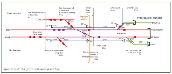
The dynamic changeover overlap interface option is based on implementing the principles of dynamic ac/dc changeover with an overlap interface (Figure 4). The proposed dual electrified section would start east of Primrose Hill tunnels. The overlap interface starts at the junction where the up and down tracks of the Watford line join the WCML and ends at the existing Camden substation (Figure 4).
The main issue with this option is dc stray currents since dc and ac rails remain bonded. A key criterion is to determine the minimum overlap length and the beacon locations so that the train always has both ac and dc supply available during a transition in either direction.
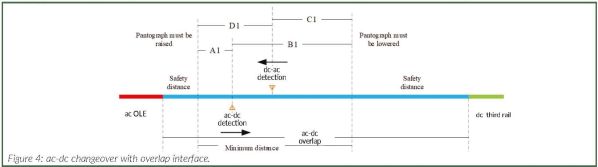
The distances A1 and B1 are the minimum required by the overlap interface and beacon location for a transition from ac to dc, while distances C1 and D1 are the minimum required for the dc to ac changeover. The distance B1 is usually larger than A1, so the location of the ac/dc beacon detection is closer to the ac side than the location of the dc/ac beacon. The distances D1 and C1 are generally comparable in length. A safety distance must be added in both directions. The safety distance on the dc side must be as large as possible to allow adequate overhead line distance and minimise the risks of early raising or late lowering of the pantograph. The safety distances on both sides, particularly for dc, must ensure that there is no gauge infringement by the device when the train is operating in both directions. The only work needed is to remove the third rail between Euston station and Camden substation.
The minimum overlap distance should be 300m for safe operation. The available overlap distance interface from Figure 5 is greater than 600m, so the case for deploying the ac/dc overlap changeover on this section is very sound. Ideally, the start of the changeover from the ac side should be located at the start of the third rail at Camden substation. This will allow the remaining overlap distance - over 300m - to continue onto the dc side of the changeover to provide extra safety distance, thereby allowing adequate time to apply some or all of the verification actions should failures occur.
In this scenario, no changes are required to the signalling system or infrastructure, so accessibility and maintainable will remain the same, while the impact on operation will be minimal as the ac/dc transition is on the move. Reliability will depend on the components constituting the system, in particular communication between the lineside equipment and the implementation of control mechanisms by the train manufacturer.
The key risks with this option are either too early raising of the pantograph on the move from dc to ac or too late lowering of the pantograph when transitioning from ac to dc. The cause of these two risks is beacon detection failure, which could be caused by a breakdown of near field communication (NFC) between the radio-frequency identification (RFID) and beacon or balise-antenna, or failure of the train reader. To mitigate these risks the location of the overlap must be as close as possible to the ac side allowing as much catenary length as possible for manual intervention to be applied and/or applying defensive control mechanisms on the train.
In conclusion, all three conventional options involve significant infrastructure changes at substantial cost and operation disruption. The fourth option of employing onboard battery will clearly be the most attractive option.